itp: digifab

[ITP: Digital Fabrication] Algorithmic Design of 2D Geometry

Overview

Danny gave us a lecture on using the algorithmic and sometimes random nature of p5.js and Processing to help design physical art pieces as a part of the digital fabrication work flow. He has code examples to export DXF and PDF from Processing and SVGs from p5.js. The assignment for this week was to export 2D geometry from code and cut it on the laser cutter.

Sketch Selection

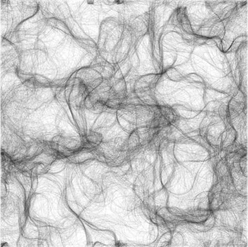
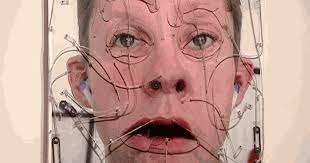
I had other presentations to do for this class this week, I knew I wouldn’t have time to come up with some new generative algorithms, so I looked through some things I had coded in the past. I considered this sketch which I wrote referencing Nature of Code. It’s lines drawn in a Perlin noise flow field but it really looks like a lot of hair! I decided though the output looked super cool, it wouldn’t bee a good candidate for laser cutting.

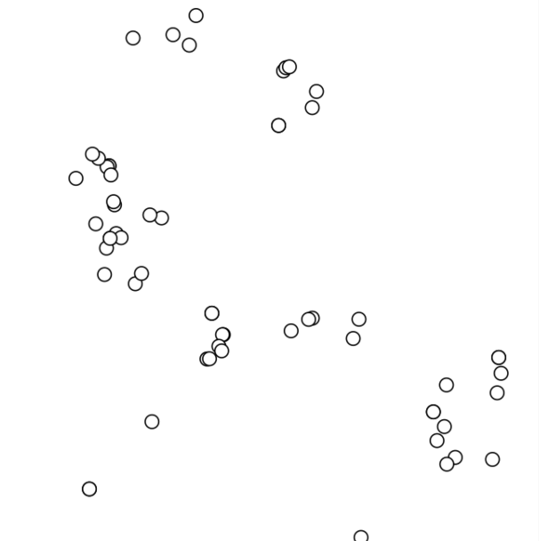
A preliminary step to the “hair” was these dots navigating a flow field. I thought this was still interesting to look at and might be a good candidate for laser cutting. I started adapting the sketch to make the dots circles with outlines to cut. Then I also made less of them because otherwise the laser might melt the material if it’s cutting in the same place over and over again.

Getting the sketch to save an SVG was difficult somehow. I was only able to get it to work by copying my code into the example Danny gave us.

Once I got this sketch to be relatively laser-cutable I didn’t like the output as much anymore. But then I remembered my flower generator sketch from a few years ago! I was able to slow down the frame rate and save SVGs from the sketch. What’s kind of funny is that whenever I would click the sketch wouldn’t export the current flower, it would export the next one. So the flowers I picked were kind of a surprise.

Once I had my SVGs, I brought them into Illustrator for some post-processing. Because of the sketch I chose, the post-processing was significant. I had to remove all colors, create outlines at the correct line width, and connect some shapes. But finally the SVGs were ready for laser cutting!

Original flower SVG

Ready for laser cutting!

Original flower SVG

Ready for laser cutting!

Final Product

[ITP: Digital Fabrication] Project Update

Big Brain Research

So I watched a series of brain and neuron videos from this great YouTube channel called CrashCourse. Here’s some of my key takeaways:

  • The brain is part of the central nervous system

  • The brain is the source of self and controls human behavior

  • Parts of the brain have specific functions yet nearly every region of the brain lights up during simple tasks

  • “Old brain” = medulla + brain stem + pons + thalamus + reticular formation + cerebellum

    • Basic bodily functions

  • Limbic system = amygdala + hypothalamus + hippocampus

    • Memory consolidation, fear, aggression, learning

  • Gray matter = two hemispheres that make up 85% of brain weight

    • Oversee thinking, speaking, perceiving

    • Corpus callosum connects the two hemispheres

    • Left = language, right = creative function, controls the opposite side of the body

    • Cerebral cortex = 20 billion neurons and glial cells for protection

  • Neurons are not only in the brain, they run the whole length of your body!

    • They respond to stimuli and transmit signals

    • They are the longest lived cells in your body, brain neurons will live as long as you do!

    • Neurons are irreplaceable ( … or are they?! In my interview with Erin she said there’s research proving otherwise…)

    • They have large appetites, 25% of the calories humans consume go to brain activity

  • Three types of neurons:

    • Sensory neurons = transmit impulses from sensory receptors to the CNS

    • Motor neurons = impulse moves from CNS to rest of body

    • Interneurons = impulse moves between sensory and motor neurons, these are the most abundant

  • Neurons transmit at one uniform strength and speed but can vary in frequency

    • The brain reads the neuron signals like binary code, organized by location, sensation, magnitude, and importance

  • Neuron action potential = depolarize resting neuron to cause a big enough change in membrane potential to trigger voltage-gated channels to open

    • Resting membrane potential = -70mV

    • Trigger threshold = -55mV, all-or-none triggering

    • A weak stimulus tends to trigger less frequent action potentials, intense signals have increased frequency to tell muscles to contract harder

  • Conduction velocity is faster for reflexes and slower for glands and guts

    • Transmission speed is affected by whether or not there’s a myelin sheath on the neuron axon

Remaining brain questions:

What purpose do the folds in the brain have?

What does anxiety, depression, poor mental health do to how the brain functions?

Moodboard - interesting connections and weird thoughts

Neurons firing (video)

Light map

Stars

big brain, smooth brain, brain fart, mind blown, brain spiral, black box, two hemispheres

Sketch

For this project I would love to build a custom PCB sculpture. Components would only be on one side of the circuit board and I’d like to build some prototypes on the Bantam Desktop mill in the ITP shop.

LEDs

I want to illuminate a series of LEDs. They need to be addressable so that I can control each pixel individually to make neuron-firing animations. I only need the LEDs to illuminate a white light. Here are a couple of options I was considering:

I ended up going for the NeoPixel mini because of its small footprint. Also, Adafruit has provided the EAGLE component that I can use for my design and I can leverage the NeoPixel library. This will cut down my work considerably! These are also a relatively affordable option as far as I can tell from my searching. I might need up to 50 pixels (or more?!) in my final sculpture, so I’ll be going through a lot of NeoPixels...

Resources

https://www.youtube.com/watch?v=pRFXSjkpKWA

https://www.youtube.com/watch?v=vHrmiy4W9C0

https://www.youtube.com/watch?v=qPix_X-9t7E

⚡️ https://www.youtube.com/watch?v=OZG8M_ldA1M ⚡️

Neuron Forest by Katie Caron

[ITP: Digital Fabrication] Bantam Othermill

Overview

The Bantam Othermill is a Desktop PCB milling machine. It is for milling printed circuit boards, small 3D parts, and engraving. A milling machine removes material from a work piece by rotating a cutting tool and moving it into the work piece.

There is also a fourth axis attachment with which you can rotate a material around the x-axis and mill away material to make 3D parts.

Working Volume

The milling area is pretty small: 4.5 x 5.5 x 1.35 inches with spoilboard installed and 4.5 x 5.5 x 1.6 inches without. There are no spoilboards installed on the mills in the shop and Phil said there was a little more wiggle room with the material thickness, more like 2 inches max.

Materials

Don’t use these:

  • Steel (stainless or otherwise)

  • Iron

  • Titanium

  • Fiberglass

  • Hard stone and precious gems

  • Glass

  • Food products

Use these:

  • FR-1 PCB blanks

  • Machining wax

  • Linoleum

  • ABS

  • Acrylic

  • Brass (for engraving)

  • Aluminum (for engraving)

  • Silver (for engraving)

For a complete list of materials you can use and tips, check out this article.

Confusion between Othermill and Bantam Desktop CNC

Othermill and Othermill Pro are both small table-top CNC mills from Bantam. They can be identified by their white plastic housing and we have many of them in the ITP shop. Bantam stopped selling them in 2017 and Phil was adamant in focusing on the Desktop machine (still being manufactured/supported) with its wider capabilities.

Othermill

Bantam Tools Desktop PCB Milling Machine

Before you begin - what you need

Design file - SVG, BRD, Gerbers, and G-code files

Milling material - cuts most any material softer than steel, for example wood, plastic, machining wax.

Milling tool - 1/32” Flat End Mill and 1/64” Flat End Mill are included, but you can use any cutting tool that has 1/8” shank. We have all the tools, bits, and things in the shop. Eventually there will be kits available for check out in the shop.

Software

You can download the Bantam Tools Desktop Milling Machine Software from here but there are computers in the shop designated for use with the Bantam machines with the software already downloaded. All you need is your design file on a flash drive.

Other softwares that might be handy are ones used for drawing and/or modeling like Fusion360, EAGLE, Inkscape, etc. The software is expecting .svg, .brd, PCB Gerbers, or G-code files. Some CAM software requires a Bantam Tools post-processor to allow for integration with the milling machine. The post-processing software translates the mill design into tool paths and machine movements specific to the Bantam.

Process - Cutting sample PCB

  1. Checkout a Bantam tool set kit from the ITP shop. Below are some of the things you might use when working with the Bantam. There’s also a drawer under the work bench with a bunch of tools and materials for working with the mill.

2. Plug desktop mill into power and make sure the computer is connected to the machine over USB.

3. Turn on the machine with the switch in the back. When it is first powered on, the mill will calibrate itself.

4. Open your design file in the Bantam 2.0 software. The software will prompt you through the setup and milling process. In the screen shot below you can see that there’s a warning. As a safety feature, the mill won’t rotate if the front door is open.

5. Start by installing the tool you will be using. The machine should be left in a state where no tools or bits are installed. If there’s any hardware already installed, feel free to remove it. For our setup, we installed the fan on the bit to remove excess material. Screw the collet into the nut and the bit into the collet. Use the two wrenches to install the tool but make sure to keep it only finger tight so it can be removed in the future.

6. The software will prompt you to go through the process of locating the newly installed tool. The machine will go through an automated process of conductively measuring the vertical distance between the tool tip and the collet so that the machine knows where the tip of the tool is in space.

7. Follow the software prompts to define the material and size. Make sure to double-check all these measurements.

8. Prep the material for install. The sheet of FR-4 will be stuck down to the bed using double-sided tape. Make sure to cover as much as the area as possible being careful to not wrinkle or double up on tape. Inconsistencies in material level will affect the cut. At some point the software will ask for z-offset so make sure to measure the PCB material with the tape, both sides of paper backing removed.

9. The software will prompt you to attach the material and push the bed forward. You can clean the bed down with rubbing alcohol. Place the material as close and lined up to the bottom left corner as possible. This is the origin. Stick the material down.

10. Confirm the placement and scale of your design and tool path. Be sure that what you’re milling was designed with the tool in mind and never place your design directly on the edge of the material.

11. Setup is complete, now we can run the mill! NOTE: the Bantam laptop isn’t currently logged into the PCB subscription needed to cut the .brd file but the shop is working on getting laptops setup for checkout with all the correct softwares and subscriptions for any digi-fab process.


Voila!

12. The last thing to do is remove the circuit board from the bed. Use the scraper to gently pry the material. You can use some isopropyl to try to loosen the adhesive. Remove all bits from the machine and put everything away.

Notes

  • Lines can only be milled if they are as wide as the width of your tool

  • Remember, the smaller the tool, the more fragile it will be and the slower you’ll need to cut. Big tools are great for roughing passes and clearing out lots of material.

  • The tool moves in the z- and x-direction, the bed moves in y-direction

Terms

CNC = computer numerical control, all of the robot-y machines in the shop are CNC’s

CAD = computer-aided design. Softwares include: SolidWorks, Fusion360, VectorWorks, etc

CAM = computer-aided manufacturing

Collet = a segmented band or sleeve put around a shaft or spindle and tightened to grip it

Shank = the end of a drill bit grasped by the chuck of the drill

Spoilboard = disposable workbench mounted above a working/milling surface

Fixturing = the process of secuting the material to the milling machine’s bed

For my own reference…

FR = flame retardant materials

FR1 = paper substrates for single-sided boards, ROHS certified

FR2 = basically FR1

FR3 = basically FR2, except it uses epoxy resin instead of phenolic resin

FR4 = glass fiber composite with a flame retardant epoxy resin, water resistant, superior electrical insulation, excellent copper adhesion, preferred for multi-layer PCBs

Resources

Bantam Tools Desktop PCB Milling Machine Documentation

Technical Specifications

Materials Overview

Bantam Tools Milling Machine Software

Light Up PCB Badge Example Project

https://www.wellpcb.com/fr1-pcb.html

[ITP: Digital Fabrication] Multi-Dimensional Drawings in VectorWorks

The assignment was to choose an existing object and try to create a scale drawing of it, in multiple views, in Vectorworks. I have never used this software before and have very limited experience in CAD other than designing PCBs.

Process

Initially I chose this mini recycling bin. This is truly my most prized possession, my boyfriend got it for me and I use it to hold all my scissors, x-acto knives, and screw drivers. It also felt like an object that would be easy enough to draw but also had some curves and interesting shapes I could learn the software with.

Below is as far as I got with my Vectorworks drawing. Turns out the curves and weird shapes were too hard. I really couldn’t find good support online for learning this software or to draw what I wanted.

I ended up switching my object to my Circuit Playground Express. I didn’t want to go back to something I already had some experience with (drawing PCBs), I really wanted to learn something new, but time was running out and this seemed like something simple enough that I could measure and draw.

To complete this drawing, I used some calipers to measure specific components to get exact dimensions. I also followed some of Danny’s videos and did a lot of googling to navigate drawing in Vectorworks. Here are somethings I noted:

  • Combined shapes using “add surface”

  • Cut out the alligator clip holes using “clip surface”

  • Used the “DIN” dimensions, but it would be really nice if you could default to those each time!

I don’t really feel like I learned enough about using this software yet. I’m still looking out for some good beginner tutorials to familiarize myself! Also, not sure which CAD software to invest time in because there are so many to choose from and not sure what’s unique to each one. I know Phil really recommends Fusion 360…

Final Drawing

Questions

How to repeat something (copy/paste) around a circle?

How to get shapes consistently equidistant from each other?

Sometimes it is hard to move shapes small, precise amounts. How to do that?

How to make my page landscape orientation?

References

https://university.vectorworks.net/mod/scorm/player.php?scoid=24&cm=92&currentorg=articulate_rise

https://www.youtube.com/watch?v=R1Pz6u3oaeY

YouTube getting started series I still wanna check out (4 parts)

Danny’s Multiple view drawing video

Danny’s Dimensioning video

[ITP: Digital Fabrication] Project ideas

Initial Brainstorm

  • Can this project be something that is part of my thesis? Not sure what that is yet…

    • Something with a motor?

  • Mill a PCB? a brain circuit or PCB sculpture

    • Mylar? bending? enclosure is the thing!

  • Learn wood working

    • Make wood guy

    • Use the router or lathe

  • Re-do old projects, Lungs specifically

  • 3D modeling

    • A project to learn Blender with

    • Do something with my 3D scans?

  • Research digital fabrication on agar agar bioplastic

  • 3D print using platic bottle filament

Inspirations

Emoter, Tim Hawkinson

Printed Circuit Bird, Kelly Heaton

Nopales, by MORAKANA

Nopales

Furby Organ, @lookmumnocomputer

Transcendance, @digitalbeing, Taezoo Park

Ben Light’s Subtraction class and 507 Mechanical Movements

Personal Aesthetic

  • Haha hehe

  • Kitsch

  • Color, maximal

  • Silly, cute

  • Girly

Themes I’m Interested In

  • Self reflection

  • Identity exploration

  • Childhood memory

  • Feminine experience

  • Open source

Ideas

Make this wood guy

Pros:

  • Wood working

  • Learn to use the CNC router (my life long dream!)

  • New piece of furniture for my house

Cons:

  • Material cost $$$

PCB sculpture

Cons:

  • Many iterations needed

  • Feels like a cop-out

  • Don’t wanna

Pros:

  • Designed many PCBs, never made my own

  • Never made a PCB sculpture

  • Could add to my Thesis

  • Learn the Bantam Othermill (2-for-1)

Do something with my (botched) 3D scans of my loved ones

Cons:

  • For what?

  • Material cost? $$$?

Pros:

  • I could finally learn how to 3D print … Laguardia Studios anyone?!

  • I could learn to use Blender maybe?

  • Physical artifacts of people I love

References

Kelly Heaton Studio

Taezoo Park